
Sound Transmission Loss in Panels
Acoustic partition sound transmission loss
Sound transmission loss in panels is subject to a number of factors.
The Sound Reduction between two spaces is dependent on all of the elements of the structure separating them.
All Sound Transmission Loss Paths need to be considered when assessing the total sound reduction value.
Sound Transmission Loss varies with frequency.
The sound pressure waves cause the material to vibrate.
This movement is microscopic, hence invisible, but cause the panel to re-radiated sound from itself.
It can also transfer vibrations into supporting members.
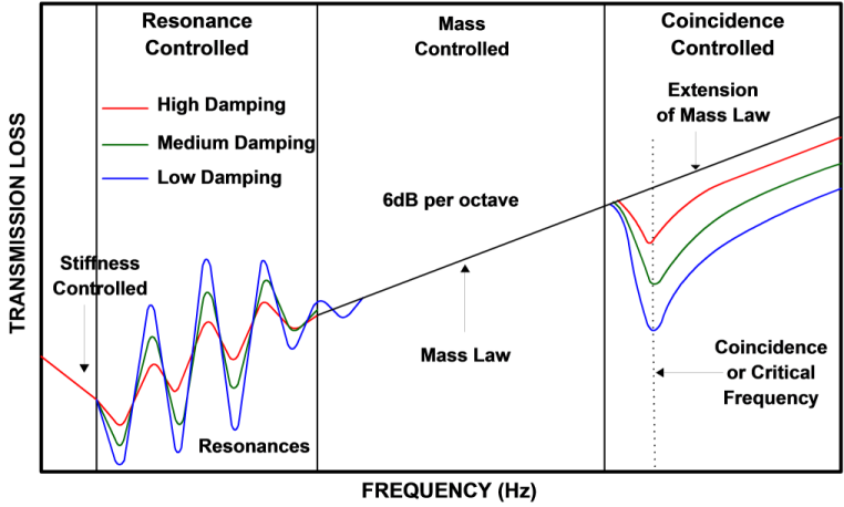
The sound reduction of a solid wall is frequency-selective as can be seen from the diagram above.
At low frequencies the stiffness of the material is the main controlling factor.
Just above this point, various resonances cause major variation in sound transmission.
At about an octave above the lowest resonance, the mass of the wall takes over and dominates the sound reduction performance.
Here the sound transmission loss depends on the surface density of the panel. It increases by 6dB per doubling of mass.
High frequencies cause bending or ripple waves through a wall. Unlike compressional waves, the velocity of bending waves increases with frequency.
The wavelength of the bending wave is different from that of the incident sound wave which created it except at one frequency.
This is the frequency at which the bending wave speed in the material equals the speed of sound in the air.
At this frequency the waves coincide, and reinforce each other, in phase.
This greatly reduces the sound reduction performance of the panel around the critical frequency.
Every material has a critical or coincidence frequency at which point the transmission loss reduces considerably.
The coincidence effect usually occurs between 1-4kHz which is the ear’s most sensitive region.
Highly damped panels are less affected by panel resonances and coincidence effects as shown in the graph.
One way to increase damping is through the use of a viscous interlayer such as our VL65.
Bending waves, excited by the incident sound, cause shear strains within the viscous interlayer material.
Because the interlayer has inherently high damping the bending waves are transformed into heat energy.
It is also worth noting that the sound reduction index at low frequencies is also affected by:- the room dimensions, the source position and the reverberation time.
These are all basically controlled by the characteristics of the two rooms.
Therefore the sound reduction index, at low frequencies, also characterises the property of the coupled room-partition-room system rather than just the property of the partition itself.
This is, in fact, true at any frequency, but it is most apparent at low frequencies, when the modal density of the rooms is low.
The sound transmission loss also varies with the direction of the incident sound waves.
It is generally assumed to be the average for all possible angles of coincidence.
Above the critical frequency, stiffness takes over to give a further, though less steep, increase in sound reduction.
The transmission of sound between rooms involves not only the direct path through the separating assembly, but also the ‘flanking’ paths around the assembly as well.
Stiff panels are needed if high performance is required at low frequencies.
Stiff panels however have a lower coincidence frequency which reduces the performance at middle frequencies.
These are the frequencies which are usually the more important in basic situations.
The best barriers are heavy, high mass, limp, highly damped materials with a high weight to stiffness ratio such as our VL65 acoustic membrane.
Mass Law
The first variable which is normally considered when designing for sound transmission loss is the mass of the panel per unit area.
An increase in transmission loss is expected with increasing mass because the heavier the panel the less it vibrates in response to the sound waves and hence the less sound energy it radiates on the other side.
The mass law (fig2.) predicts that the transmission loss will increase by approximately 6 dB for each: doubling of the surface mass or doubling of the frequency.
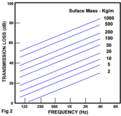
The mass can be increased by using thicker material or denser material.
Theoretically, all noise control problems could be solved by increasing the partition mass, however, practical considerations limit the usefulness of this option.
Coincidence Dip
In practical situations, the measured transmission loss often differs from that determined theoretically from the Mass Law.
The typical Transmission loss for some common building materials is illustrated in Fig3. As would be expected, the greater mass of the concrete exhibits much higher transmission loss than a sheet of plywood.
However, significant deviations from the mass law are evident for all three materials.
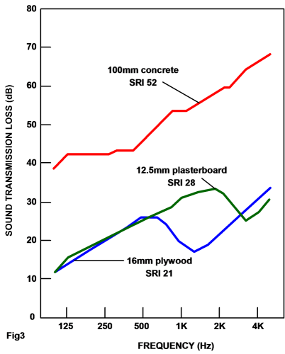
The curves for plasterboard and plywood (both around 10kg/m²) show very similar transmission loss at low frequencies, increasing steadily in accordance with the mass law.
At higher frequencies, each material exhibits an appreciable dip, called the coincidence dip.
This dip is centered at the coincident or critical frequency which in turn depends on the materials stiffness and thickness.
The coincidence dip is at a lower frequency for the plywood because the plywood is stiffer than the plasterboard.
Even though the plywood and plasterboard weigh the same the plywood has an overall Rw lower due to the dip.
The depth and width of the coincidence dip are determined by losses of sound energy in the material and energy transfer to the supporting structure.
The greater these losses, the shallower and broader the coincidence dip, and the less it affects the transmission loss.
When two layers of material are glued firmly together they behave like a single thick layer with an associated lowering of the coincidence frequency.
However, if the layers are attached more loosely, permitting surface slippage during bending motions, the coincidence dip does not shift to a lower frequency and friction between layers can increase the energy losses producing a higher transmission loss near the coincidence frequency.
Partitions divided into two or more cavities can provide high transmission losses with lightweight constructions.
However, this potential increase in performance may be limited by structural couplings between the layers.
The transmission loss of a cavity construction depends strongly on the characteristics of the space in-between.
Mass-Air-Mass Resonance
There is a practical basis for designing a minimum spacing between cavity layers. when sound waves strike a partition they cause it to vibrate.
The air trapped in the cavity between the layers acts like a spring transferring vibrational energy from one layer to the other.
This energy transfer is significant only in a small frequency range where it causes a sharp lowering of the transmission loss.
The frequency of the mass-air-mass resonance depends on the mass of the layers and the distance between the layers.
The larger the air-space, or heavier the materials, the lower the frequency at which resonance occurs.
To maximise the improvement due to the air-space, partitions should be designed so that the mass-air-mass resonance is as low a frequency as possible.
Many common partitions don’t meet this criterion and the resulting deficiency is a lack of low frequency performance.
Filling the cavity with absorptive material can increase the transmission loss substantially especially if the cavity is large.
However, it should be noted that cavity absorption is only really beneficial if there are no structural connections between the surfaces.
Structural connections will tend to ‘short circuit’ the absorption benefits because of the dominant vibrational energy path through the studwork.
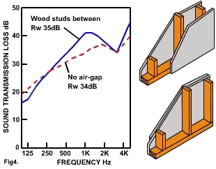
Fig4. compares the transmission loss of a conventional wood stud wall with that of both layers of plasterboard attached to one side only, eliminating the air-space.
Because of the vibrations transmitted through the studs, the air-space between the two layers of plasterboard gives little improvement.
At low frequencies the cavity actually gives a lower sound transmission loss because of the mass-air-mass resonance.
For plasterboard construction there are several practical ways of reducing mechanical connections between partition layers.
These include staggered wood studs separate rows of studs steel studs resilient bars.
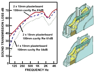
Fig5. shows the sound transmission loss in panels with a single layer of 15mm ‘firecode’ plasterboard on each side, supported by 90mm structural steel studs with 16mm resilient metal channels on one side – the Rw rating for this is 54.
At the lowest frequencies, the transmission loss drops rapidly because of the mass-air-mass resonance, hence bass notes will be transmitted quite well.
To improve the sound transmission loss, it is necessary to increase the weight of the surface layers and/or increase the distance between the surfaces.
Adding a second layer of the same plasterboard, on each face, increases the Rw rating to 61dB. The sharp drop in transmission loss near 100Hz is shifted to a lower frequency.
Increasing the cavity space (90mm to 150mm) gives an even higher Rw rating of 63dB. This significantly improves the transmission loss at the lowest frequencies.
For the mid and high frequencies, vibration transmission through the studs limits the improvement due to the increased air-space.
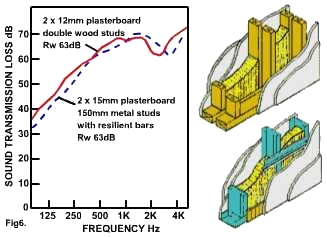
In comparison, Fig6. shows the transmission loss for a double wood stud partition.
The slightly larger cavity depth and reduced structural connection through the studwork gives the same Rw rating as those in Fig5, but with lighter surfaces.
The mass of standard 12mm plasterboard is around 30% lower than that of 15mm ‘firecode’ board.
Using the heavier plasterboard with the double stud arrangement would give an even higher performance rating.
When designing an acoustic partition, the importance of a large air-space should be remembered.
Although adding weight will generally increase the transmission loss, adding a layer in the wrong place can reduce the effectiveness of the air-space and thus lower the transmission loss.
The illustrations below summarises how the sound transmission loss in panels with more layers, but in the wrong place, can sometimes mean less performance when acoustics are concerned: